views
90º Stub Up Bend
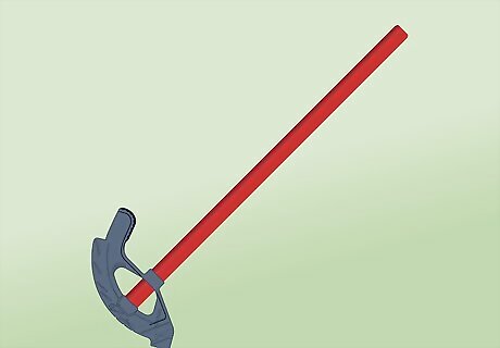
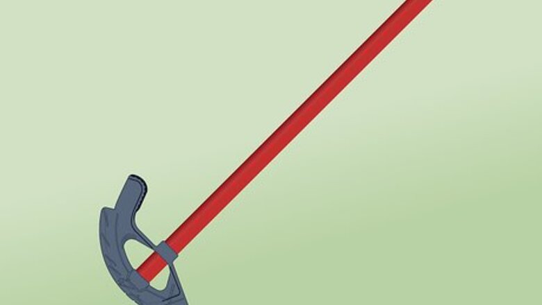
Select the correct bender. Make sure your bender is designed for EMT conduit of the size you are using. Even a universal bender may require attaching a shoe and/or follow bar designed for EMT. This article focuses on hand benders. If you are using a hydraulic or power bender (recommended for conduit with a nominal size over 2 inches), find instructions for your specific bender model. Hickey benders tend to crush or kink EMT conduit. Use a bender with a curved track for the conduit to slot into.
Measure the desired length of the stub. A stub up bend is a 90º bend near the end of the conduit. Measure the distance on the wall from the end of the conduit to the position of the bend.
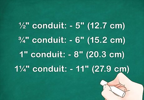
Subtract the take-up height. The radius of the bend will add extra length to the bent end of your conduit. Take this into account by subtracting a certain amount from your measurement: If you are using ½" EMT conduit, subtract 5" (12.7 cm). ¾" conduit: subtract 6" (15.2 cm). 1" conduit: subtract 8" (20.3 cm. 1¼" conduit: subtract 11" (27.9 cm).
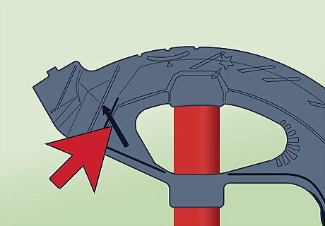
Line the arrow mark on your bender to this measurement. Place your conduit on the floor. Measure from the end of the conduit to the new length you calculated, and mark the conduit at this point. Line the arrow symbol on your bender up so it points to this mark. Slot your bender onto the conduit. Make sure the bender handle is angled toward the end you measured from. If your bender does not have an arrow symbol, you may need to find the instructions for your
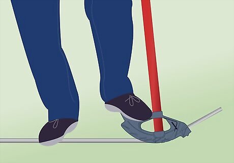
Press down on the foot pedal to bend the conduit. Your foot should provide most if not all of the pressure. Without pulling, use one hand to steady the handle on your bender, and the other to steady the conduit end once it rises within reach. Apply firm, constant foot pressure, as a pause could create a kink in your conduit. Bend until the end of the conduit is vertical, or very slightly past vertical. A conduit bender will allow you to make any type of bend, from a few degrees up to 90°. You can also use a bender to make an offset, or hump. If your conduit is 1¼" or larger, you may need an assistant to operate the handle.
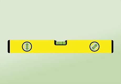
Confirm the bend with a spirit level (recommended). Attach a level to the vertical length of conduit. If necessary, make small adjustments to the bend until the bubble of the level is centered. The conduit will flex back slightly after you remove the bender, so bending slightly too far will provide the best results.
Back to Back Bend
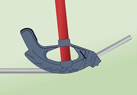
Make a stub up bend. "Back to back" refers to a distance from the back of one 90º bend to the back of the other. In other words, this is the distance between the two parallel lines of a U bend, measuring from the outside edges. To create the first bend of the U, follow the instructions above for a stub up bend.
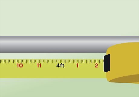
Measure the distance the conduit needs to fit between. Measure the distance the two bends need to fit between, such as the distance between two parallel walls.
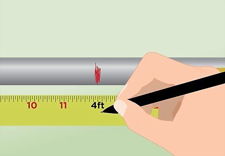
Mark this distance on your conduit. Place the bent stub end of the conduit against a wall. Measure from this wall along your conduit, to the desired length. Mark the conduit at this length using a permanent marker or pencil.
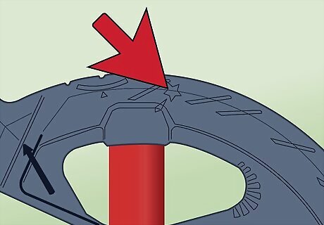
Line the star symbol on the bender to this mark. Unlike the placement for the stub bend, the bender's handle should be pointed away from end you measured from. For bends like this, line the star symbol on your bender head up with the mark. If your bender does not have a star symbol, refer to your bender's instructions. If the distance between the bends is too short for your bender, use the stub up system instead. In other words, turn your bender the other way, subtract the take-up distance described in the stub-up section, and line the conduit up with the arrow mark instead.
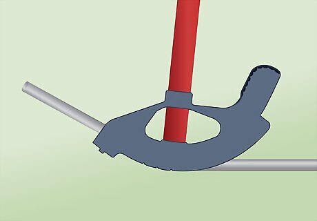
Bend the conduit. Place the length of conduit you measured flat on the floor. Apply firm pressure on the foot pedal until the conduit bends to a 90º angle. Checking this angle with a level is highly recommended, since it's important that the two bends of the U are parallel.
Offset Bend
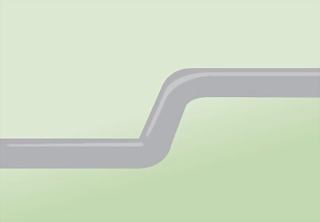
Use offset bends to shift the position of the conduit. An offset bend requires you to bend the conduit in two places at opposite angles, usually between 10 and 45 degrees. Use this to shift the conduit to avoid an obstacle or change elevation, the continue in its original direction.
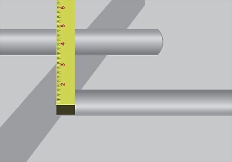
Measure the depth of the offset. Measure the distance between the two parallel locations where the conduit will run before and after the bend. Measure at right angles, not along the bend. Always measure between two identical positions on the conduit (base-to-base, center-to-center, or top-to-top). Do not rely on the nominal diameter of your conduit, which is slightly smaller than its actual size.
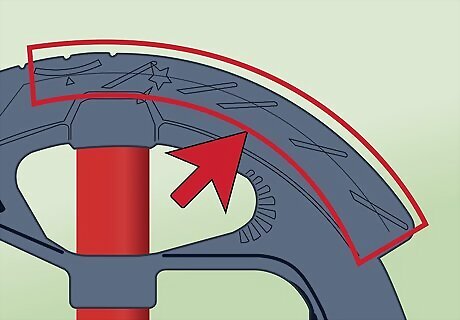
Choose an angle for the bend. As a general rule, the shorter the offset distance, the smaller the angle. An offset of a few inches can use a 10º or 22.5º angle, but an offset of several feet may call for 30º or 45º. Smaller angles will "use up" less of your conduit, but may be more difficult to bend precisely. If your conduit layout requires precise measurements, calculate the amount of shrinkage, or additional length required for the bend: A 10º angle uses an additional 1/16" of length per inch of offset depth. A 22.5º angle uses 3/16" per inch of offset depth. A 30º angle uses ¼" per inch. A 45º angle uses ⅜" per inch. A 60º angle uses ½" per inch. To find the total shrinkage, multiply the offset depth in inches by the shrinkage value above.
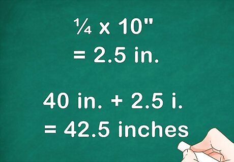
Find the position of the far bend. Find the total shrinkage using the instructions in the previous step. Add this number to the distance from the end of your conduit to the obstacle. Mark the conduit at this length. Here's an example for a conduit you plan to bend at a 30º angle to overcome a 10" step: The shrinkage for a 30º angle is ¼ inch per inch of rise. (See previous step.) Multiply ¼ by 10 inches of rise: ¼ x 10" = 2.5 inches. This is the total shrinkage. Let's say the conduit will run from an electrical box 40 inches from the step. Add this distance to the shrinkage: 40 inches + 2.5 inches = 42.5 inches. Measure 42.5 inches from the end of the conduit and mark it with a marker or pencil.
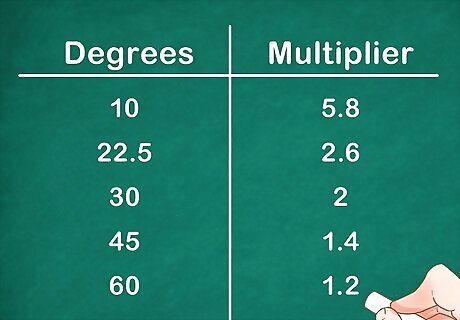
Use the offset multiplier to find the distance between the two bends. Each angle has its own offset multiplier, listed below this step. Multiply this value by the offset depth to get the length between your two bends. For a 10º angle, multiply the offset depth by 5.8. For a 22.5º angle, multiply offset depth by 2.6. For a 30º angle, multiply by 2. For a 45º angle, multiply by 1.4. For a 60º angle, multiply by 1.2. Some benders list the offset multipliers on one side of the head, directly opposite the corresponding angles on the other side. These may not match the numbers above perfectly due to rounding.
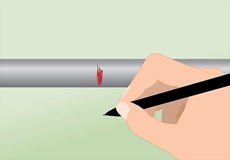
Mark the position of the near bend. Place the tape measure against the first mark you made, for the far bend. Measure back toward the end of the conduit, until you get to the length you calculated. Mark the conduit at this spot, the position of the near bend. Follow this example if you're having trouble with this step: Return to the earlier example of a 30º angle up a 10" rise. A 30º has an offset multiplier of exactly 2. Multiply the offset depth (10") by 2 to get 20". Place the tape measure against your first mark, 42.5" from the end (calculated in the steps above). Measure 20" toward the end of the conduit and make another mark. This is the position of the other bend.
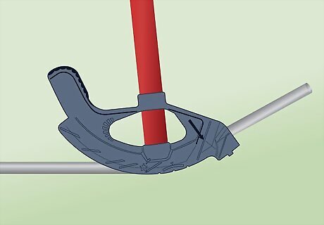
Bend the far bend using the stub up system. Place the conduit on the floor. Line up the arrow on your bender with the mark farthest from the end you measured from. (This is the first mark you made.) Slot the bender onto the conduit, and apply steady foot pressure to bend the conduit. Watch the degree mark on the side of your bender that matches the angle you chose. Continue bending until this mark touches the horizontal portion of the conduit. Position the bender so the foot pedal is between the two marks. For example, if you plan to bend at a 30º angle, bend until the 30º mark touches the edge of the conduit. You can use any mark on your bender instead of the arrow, as long as you use the same mark to create the second bend. A different mark may be more convenient for bends near the end of the conduit.
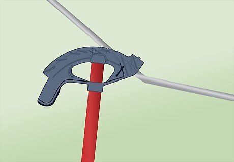
Flip the conduit and bender upside down. To prepare for the second bend, leave the bender attached to the conduit. Pick up the bender and place the handle end on the floor, leaning it against your leg to keep it stable. Slide the bender back toward you until the arrow lines up with the second mark on your conduit.
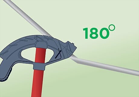
Roll the conduit 180º. Without taking it out of the bender, rotate the conduit exactly 180º. Sight along the conduit to make sure the bent end lies along exactly the same plane as your bender. If the bend is sticking out to one side, your conduit will not lie flat. You may lean the bent end down against the ground to support it.
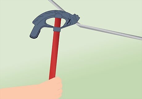
Create the second bend by hand. Brace the bender handle against your foot and leg. Confirm the arrow on the head still lines up with the mark you made. Grip close to the bender head and pull slowly down until the conduit touches the desired angle mark on the bender. The farther away you hold the conduit, the less accurate the bend will be. Grip as close to the mark as you can without making the task unreasonably difficult.
Three Point Saddle Bend

Familiarize yourself with other bends. A three-point saddle bend raises the conduit in a triangle to clear a narrow obstacle. This requires calculations and techniques described above in the offset bend method.
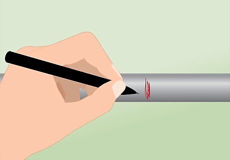
Mark the position of the center bend. The three-point saddle includes one bend to lift the conduit off the floor, a second bend to bend it down over the obstacle, and a third bend to make the conduit level with the floor again. Calculate the position of the center bend as though it were an offset. For example, conduct these calculations for a 30º–60º–30º saddle, the easiest setup to memorize: A 30º creates ¼" shrinkage for each inch of rise. Multiply ¼" by the height of the obstacles in inches to find the total shrinkage. Measure the distance from the desired position of the conduit end to the center of the obstacle. Add these two values together. Measure this length from the end of the conduit and mark it. Note: Many benders only have a teardrop mark to show the position of a 45º saddle bend. In this case, a 22.5º–45º–22.5º saddle is the easiest type to bend.
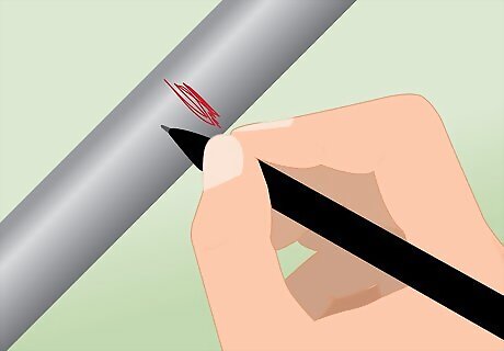
Mark the positions of the two other bends. Calculate the distance between bends as you would an offset. Measure this distance twice, starting from the center mark and measuring in both directions. For example, since a 30º angle has an offset multiplier of 2, a 3" high obstacle requires bends 2 x 3" = 6" apart. Draw a mark 6" to the left of the center mark, and another mark 6" to the right of the center. Instead of calculating this by hand, you can look up a Three-Point Saddle chart online to give you these values.
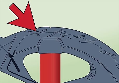
Bend the center. Most benders have a teardrop mark used for the center of a 22.5º–45º–22.5º saddle. Others may have three notches or marks along the rim, next to a "center bend" mark that looks like a semicircle with an arrow at the center. These three notches correspond to 30º, 45º, and 60º angles. Line up the appropriate mark with the center mark on your conduit, and bend until the conduit touches the correct angle mark on your bender.
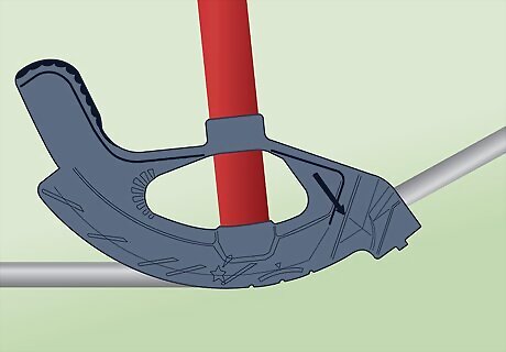
Complete the saddle bend. Turn the conduit over and brace the handle against your foot, as you would to finish an offset bend. Rotate the conduit exactly 180º in the bender so your bend is in the correct direction. Line up the arrow mark on your bender with one of the marks on your conduit, and bend to exactly ½ the angle of the center saddle bend. Repeat for the third bend of the saddle.


Comments
0 comment